What Are Linear Actuators?

What Are Linear Actuators?

Linear actuators convert rotary motion into precise linear motion for automation in robotics, CNC machines, and industrial systems. Two primary shapes exist: rod-style actuators, featuring a cylindrical design with a central screw that extends and retracts a rod for single-axis applications, and profile-style actuators, built around square or rectangular frames with drive mechanisms like screws or belts. These support a carriage guided by bearing systems, such as plain bearings or ball bearing rails, for smooth multi-axis X-Y-Z motion. PBC Linear® profile-style actuators, like the Compact Screw Driven Series or MTB Belt Driven Series, offer versatile drive options powered by motors or hand cranks, optimizing precision and flexibility in manufacturing and automation.

Contact our application engineers for more assistance in selecting the best linear actuator design for your application.


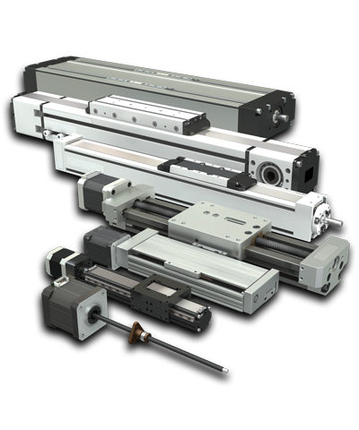
What are the main types of linear actuators?

There are four main types of linear actuators: hydraulic, pneumatic, electric, and mechanical. Hydraulic linear actuators rely on compressed fluid for movement while compressed air powers pneumatic actuators. PBC Linear specializes in electric and mechanical linear actuators meaning our actuators are driven by lead screws, ball screws, and belt drives as well as options for motor driven systems.

We offer a variety of carriage types, drive components and motor options so customers can customize the linear actuator solution that is best suited for their linear motion application. 

Carriage Options: 

  • Plain Bearings: Self-lubricating FrelonGOLD® surfaces ensure maintenance-free operation with smooth, quiet performance, vibration damping, shock resistance, and contamination resistance. 
  • Cam Roller: High-speed capability with support for cantilevered loads, corrosion-resistant stainless-steel raceways, and contamination resistance. 
  • Profile Rail: High precision, rigidity, and speed, offering increased stiffness, preloaded bearings, and low friction for enhanced support of cantilevered loads. 

Drive Options: 

  • Lead Screw: Delivers precise, smooth, and quiet operation with self-lubricating and maintenance-free properties, available with standard or anti-backlash nuts. 
  • Ball Screw: Designed for high-load applications, providing stiffness and support for cantilevered loads with various accuracy classes and preloaded nuts. 
  • Belt Drive: Ideal for high-speed, long-stroke tasks, offering contamination protection and minimal maintenance with lubrication-free operation. 

Motor Options: 

  • Integrated Lead Screw Stepper: Compact design eliminates the need for a coupler, reducing overall cost. 
  • Servo & Step Servo: High torque density, low inertia, and IoT compatibility for enhanced performance. 
  • Integrated Stepper (Smart): Space-saving design with built-in motor and drive, reducing wiring complexity and enabling IoT support. 
  • Hand Crank/Wheel: Cost-effective option for short-stroke, low-duty applications.  

Click here to learn more about the wide range of linear actuators offered by PBC Linear. 

What is the main function of linear actuators?

Every linear actuator is a device which converts some type of rotary force and applies it to achieve an in-line or linear movement. This force could be coming from a hand crank or electric motor transferred through some type of screw for example. This motion can be used to move, position, or control various mechanical systems in applications ranging from industrial machinery to medical equipment. 

Why are linear actuators so expensive?

Linear actuators are advanced systems built with high-precision components and a durable design, making them ideal for heavy-duty applications. Their superior technology and engineering contribute to the higher cost, but they offer significant value. Most linear actuators are ready to use right out of the box, requiring minimal modifications, which helps reduce downtime and saves on installation costs, providing a seamless, plug-and-play solution for customers. 

Are there less expensive alternatives to linear actuators?

In addition to complete linear actuator systems, PBC Linear also offers lead screw and ball screw driven servo motors. These lower cost options are excellent alternatives for applications that may require less precision. 

How strong are linear actuators?

PBC Linear provides nine distinct families of linear actuators, each designed to excel in handling various loads, strokes, and operating environments. For example, our Simplicity® Linear Actuators can accommodate carriage loads up to an impressive 83,000 N (18,750 lbf), making them ideal for demanding applications where reliability and strength are critical.

Mechatronics Figure 1

Benefits of Linear Actuators

Simplified and Flexible Mechanical Design

Combining the mechanical, electrical, and control elements of engineering creates a simplified design that is flexible and more user friendly. A one-unit, compact design reduces the number of components as well as space needed for installation. Less components means less labor invested, reduced time spent in setup and maintenance, and maximized operational uptime.

Optimized Performance, Productivity and Reliability

In a variety of situations, linear actuators have proven to be a more reliable solution due to their enhanced features and functionality. For example, in the internet of things (IoT), linear actuators provide the following benefits:

  • Reduced Troubleshooting
    With fewer components and less wire connections, the job of tracing down problems that may arise is greatly reduced.
  • Streamlined Commissioning
    Pre-programmed homing routines and distributed control reduces installation times and allows report progress via internet connectivity. It also allows an operator to make in-process adjustments at an individual axis without affecting the PLC or entire production line.
  • Automated Adjustments
    Increase manufacturing flexibility and speed. In addition, adaptive control is possible with conditions monitored and adjustments made locally, in real time, and right at the actuator level, without having to route instructions through the PLC.

Increased Efficiency, Decreased Costs

Combining various engineering subfields into the same design not only makes it safer, more efficient, and cost effective. Examples of efficiency and cost effectiveness of mechatronics in an IoT environment include:

  • Maximized Uptime
    Real time monitoring of temperatures, friction, motor torque, and other performance related data can be routed to a mobile device allowing the human decision maker to proactively handle issues related to maximizing machine uptime.
  • Preventative Maintenance
    Established timeframes for periodic maintenance based on cycles, number of pieces run, or other dynamic conditions can be monitored and reported to any IoT connected device such as a work station, tablet, or mobile phone, allowing teams to proactively keep machine running at peak efficiency.
  • Increased Output
    Mechatronics solutions drive greater flexibility, less down time, increased performance, and greater bottom-line output for manufacturers, assembly lines, packaging equipment, and production equipment.
Mechatronics Figure 2

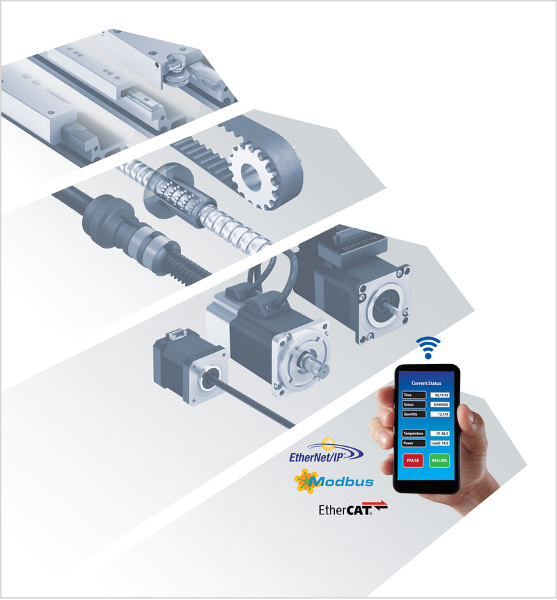
Designing a Linear Actuator System

There are several factors to consider when designing a linear actuator into a linear motion application. When designing a system with linear actuators, consider these key elements to ensure optimal performance: 

  1. Configure Your System Axis: Understand the load, moments, and required speed. Determine if an external linear guideway is needed for support, and calculate the necessary body length. 
  2. Select a Drive Type: Choose motor options pre-mounted and tested by PBC Linear, motor mounts to provide your own motor, or a hand-driven system. 
  3. Mounting Options: Decide how to mount the axis with available options like dovetail clamps and riser plates. 
  4. Limit Switches and Sensors: Select end-of-travel and home limit switches or sensors, considering both mounting type and location. 
  5. Cable Carrier Selection: List all cables to be run through the carrier and calculate the required cross-sectional area to choose the appropriate size. 
  6. Multi-Axis Systems: Repeat the process for each axis if a multi-axis system is needed.