

Belt Driven Linear Actuator w/ 1000mm V-Rails UGT040D-B21-1000-BD1B4-00L0-0 NEMA 23 Motor
- Guidance: Cam roller V-guide (CRT)
- Rail Profile: Tall rail
- Drive: Belt drive
- Rail Length: 1000 mm
- Approx. Weight: 6.7 lbs
- Motor Option: NEMA 23
Belt-driven linear actuator with a pair of parallel 1000mm-long v-rails and a v-wheel carriage, a 40mm-tall, 40mm wide aluminum rail profile, and a programmable NEMA 23 stepper motor for moving and accurately positioning loads. The motor drives a belt connected to the carriage, whose sealed stainless steel v-wheels roll along the parallel v-rails to provide smooth, stable linear motion. The tall-profile rail assembly provides structural rigidity and maintains carriage alignment during travel. PBC Linear's SIMO® manufacturing process machines aluminum extrusions with synchronized cutters in a single pass, achieving twice the flatness and dimensional tolerances of 0.050mm. The actuator supports a maximum horizontal load of 880N and a maximum stroke of 800mm.
- Belt-driven linear actuator for moving & accurately positioning loads
- Linear V-rail height: 40mm width: 40mm
- Pair of parallel V-rails of length: 1000mm
- NEMA 23 programmable stepper motor included
- Belt drive converts motor rotation into linear carriage movement
- Sealed stainless steel V-wheels roll along angled rail surfaces
- Tall-profile aluminum rail provides structural rigidity
- Rolling-element carriage guidance for smooth, controlled motion
- Maximum horizontal load: 880N
- Maximum stroke: 800mm
- SIMO® machining process provides 2× better rail flatness
- Precision-machined aluminum rail with 0.050mm tolerances
- Single-pass synchronized machining improves rail alignment
- Applications: Industrial automation, material handling and equipment positioning
Belt Drive System Horizontal Motor Mount
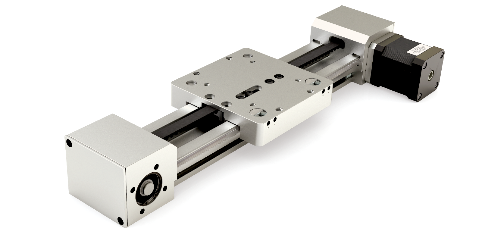
Overview
- Horizontal motor mount available in the tall profile (UGT) only
- Ideal for higher speed, high duty cycle applications
- Belt material: nylon covered, fiberglass reinforced, neoprene
- Temperature range: 0° C to +80° C (32° F to 176° F)
- Rounded GT®2 tooth design creates better engagement with the pulley resulting in greater torque transfer, reduced vibration, and extended life
Motor Options and Benefits
- Standard integrated screw stepper motors
- 42 mm (NEMA 17)
- 56 mm (NEMA 23)
- Split collar connection to integrated pulley
- Integrated shaft reduces pulley runout
- Reduces system cost
- Optional stub shaft and motor adapter plate – consult factory
Accessories
- Sensor brackets
- Toe clamps and t-nuts
- Covers
- Optional motor mounts

Split collar drive shaft connects integrated pulley shaft and motor

Independent belt clamps allow for tensioning adjustments

Idle end pulley incorporates integrated shaft design
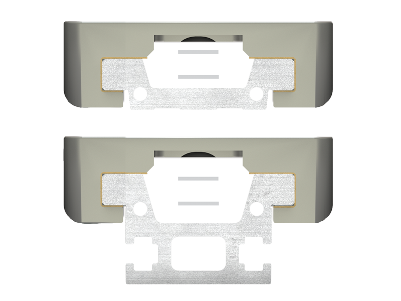
GST
Plain Bearing
Tall Rail Only
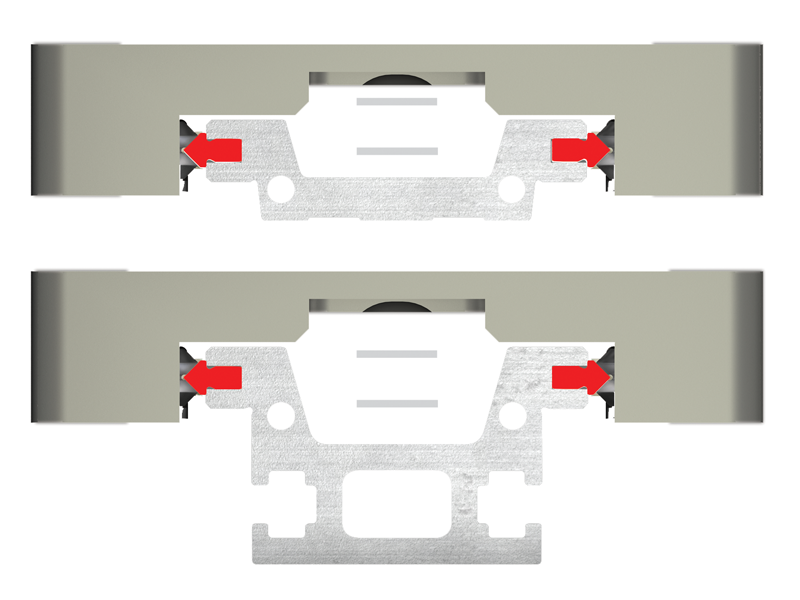
CRT
V-Guide
Tall Rail Only
| Basic System Properties | |||
|---|---|---|---|
| MAX Velocity, no lube, continuous motion | m/s | 1.5 | Requires Lubrication |
| MAX Velocity, intermittent motion or with lube | m/s | 4.2 | 5.5 |
| MAX Acceleration *** | m/s2 | 50 | 50 |
| Stroke Length (MIN recommended) | mm | 5 | 5 |
| Stroke Length (Maximum) | mm | 1900 | 1900 |
| Belt Type & Size | GT®2 - 5 mm | ||
| MAX Drive (input) Torque | Nm | 2.31 | |
| Pulley Ratio | mm/rev | 80 | |
| Pulley Pitch Diameter | mm | 25.5 | |
| MAX Drive (input) Speed | rpm | 3000 | |
| Normal Operating Temperatures - MIN – MAX | °C | 0° - 80° | |
| Carriage Weight | Kg | 0.235 | 0.355 |
| Rail + Belt Weight | Kg/m | 1.73 | 1.98 |
| System Weight (excluding motor) | Kg | 0.5 + (1.73 * length) | 0.62 + (1.98 * length) |
| Static & Dynamic System Properties | ||||
|---|---|---|---|---|
| MAX Static Load* | Fx | N | 200 | |
| Fy | 3150 | 740 | ||
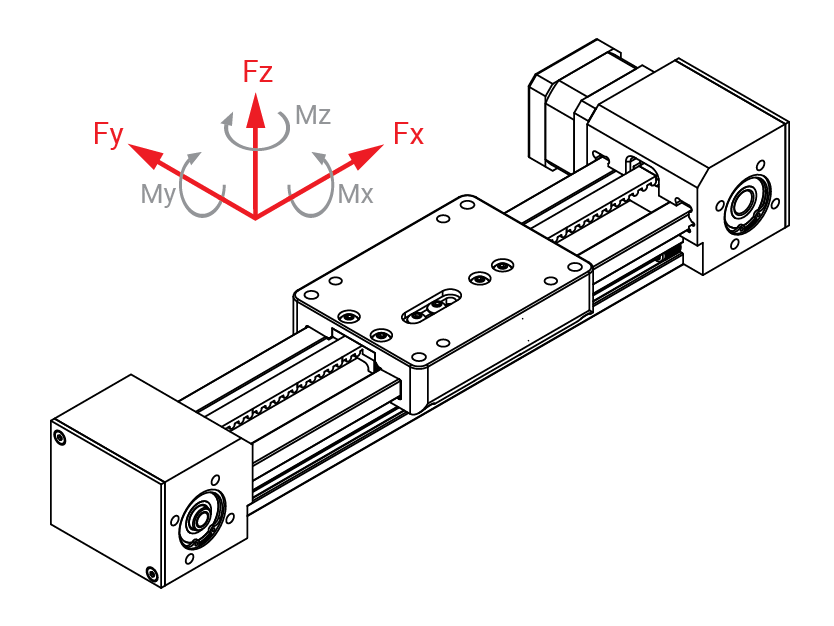
| Fz (Normal) | 4710 | 880 | ||
| Fz (Inverted) | 1640 | 880 | ||
| MAX Dynamic Load* (For PBC Linear supplied motor, refer to charts below) |
Fx | N | 200 | |
| Fy | 1600 | 740 | ||
| Fz (Normal) | 1600 | 880 | ||
| Fz (Inverted) | 1600 | 880 | ||
| MAX Moments* | Mx | Nm | 100 | 15 |
| My | Nm | 130 | 25 | |
| Mz | Nm | 120 | 35 | |
| Coefficient of Friction (linear guide) | μ | 0.125 | 0.02 | |
*The above moments and loads are MAX values, please consult our technical department for further information.
**Refer to Assembly Procedure for combined load calculations.
***Increased acceleration may be possible in limited cases. Consult factory if exceeding limit.
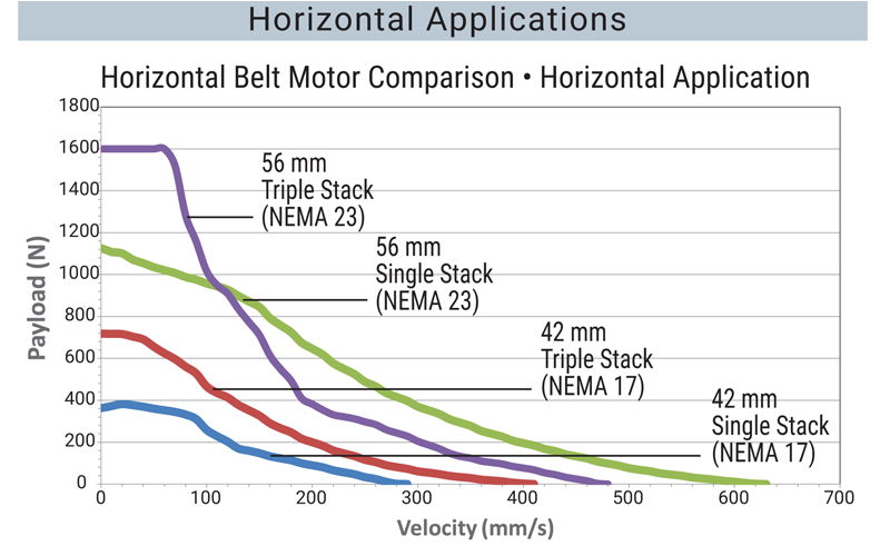

Note: Based on 2 m stroke, .125 C.O.F., and .3G acceleration. Use caution when applying a belt drive in a vertical application. Higher voltage amplifiers may produce higher speeds.
System Dimensions
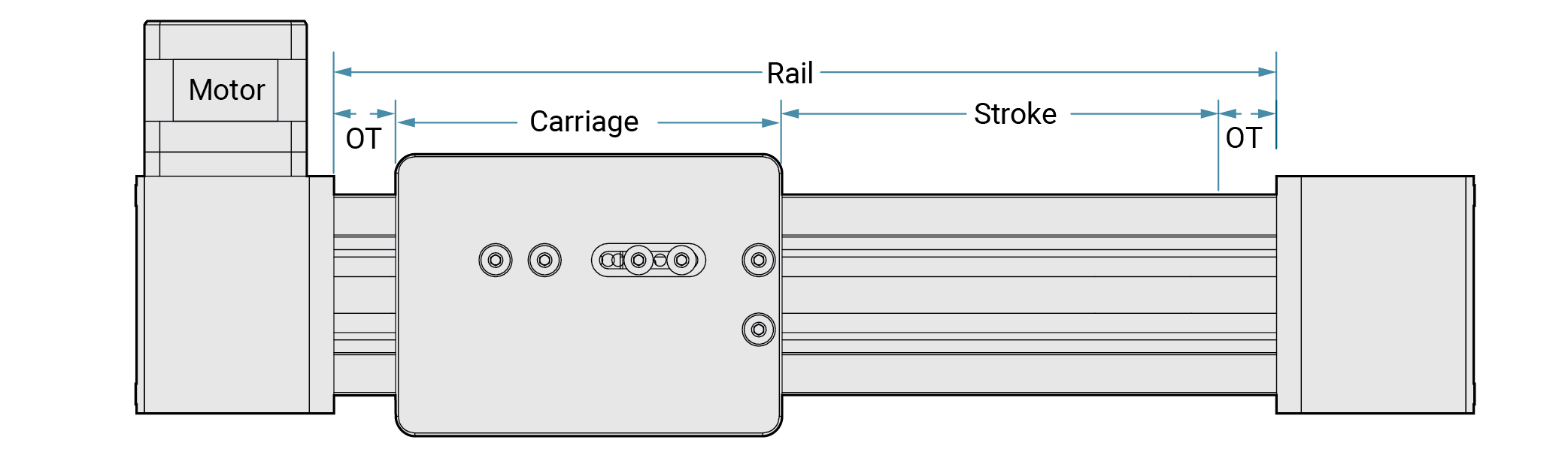
Top View
Side View
Paragraph
Side View UGT Tall Rail
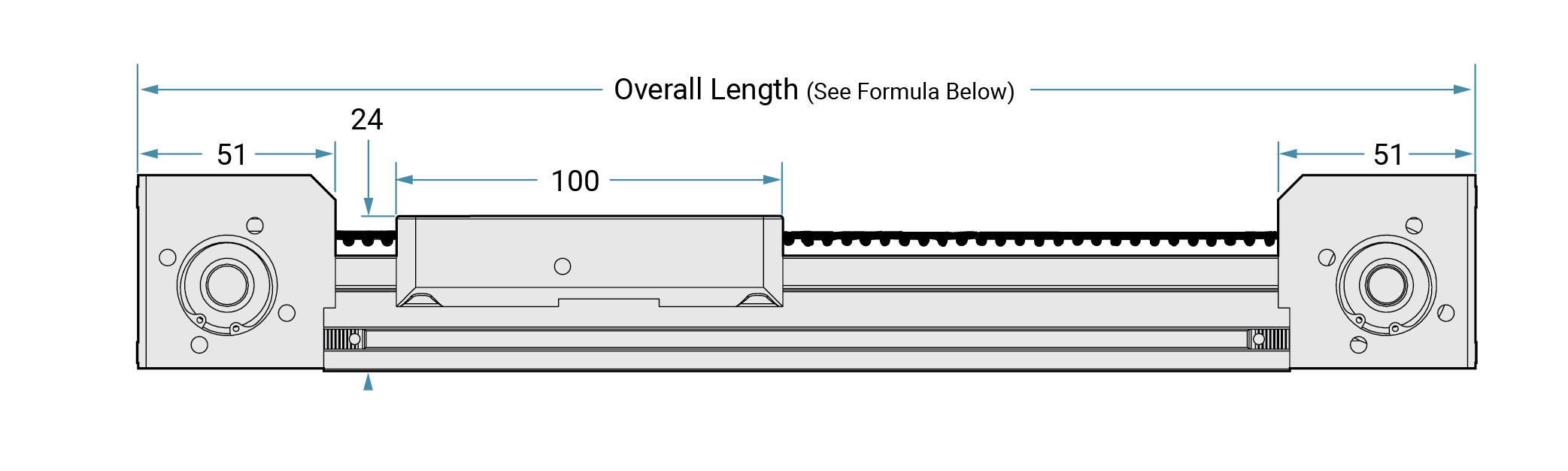
Note: GST bearing system shown
Motor Lengths (Plus Mounting Plate)
| Motor Size | Single Stack | Double Stack | Triple Stack |
|---|---|---|---|
| 42 mm (NEMA 17) | 40 mm | 48 mm | 61 mm |
| 56 mm (NEMA 23) | 55 mm | 77 mm | 77 mm |
Required for SIMO Series driven systems:
Minimum overtravel (OT)
- 10 mm for ≤ 300 mm stroke
- 25 mm for > 300 mm stroke
Motor Locations
Left
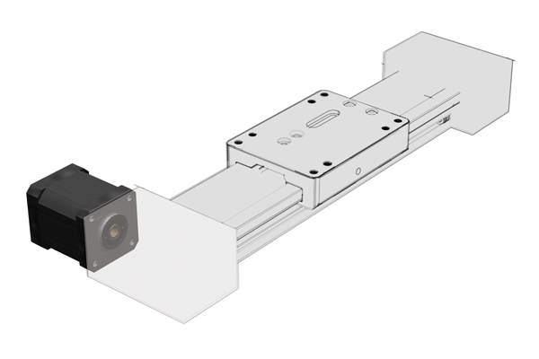
Right
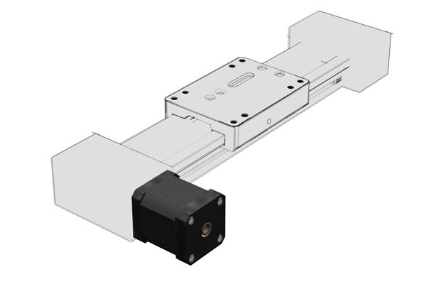
Note: Specify motor location (in part number) for PBC Linear integrated motors. Contact factory for stub shaft and optional motor mounting plates.
Top View
Carriage Dimensions
Gliding Surface Technology Plain Bearing
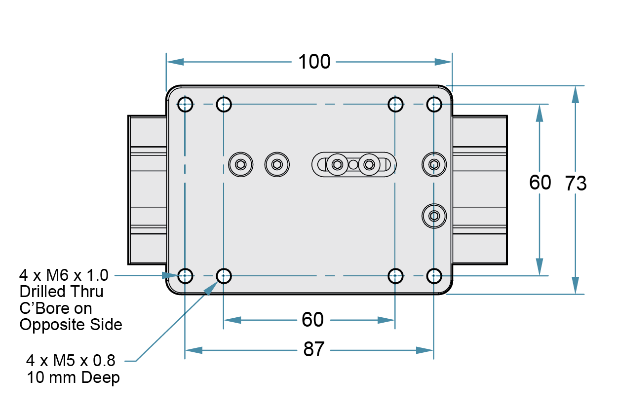
Cam Roller Technology V-Guide Bearings


