Redi-Rail Preload, Mounting, and Orientation

Redi-Rail Preload, Mounting, and Orientation

Redi-Rail is a great alternative to profile rail, where high speeds, precision, and moderate load applications are required. It offers strength, ease of installation, and corrosion resistance making it the perfect linear motion solution across a broad range of applications such as automation, machine transfer, and material handling. Redi-Rail linear guides are available in inch formats, or in metric systems equipped with wipers and patented side pre-load adjustment.

This is one of two articles that explores the properties and features of Redi-Rail linear systems. In this article we focus on establishing load orientation, fastening rails, and setting your preload.

Discover your ideal linear motion solution:


Quick steps to completing your Redi-Rail® installation

Redi-Rail® linear guides are a versatile product that combines lightweight aluminum anodized rails integrated with hardened steel races for precise travel and durability. The rollers are designed for high speeds (8 m/s) and medium loads (up to 5900 N). Redi-Rail is used in a variety of applications ranging from multi-axis positioning in robotic pill dispensing to automated vending kiosks, and large format door guidance.

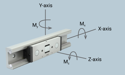
XYZ Axis diagram
Load Orientation

In order for Redi-Rail to be successful in its applied industry, installation of the Redi-Rail system must be done properly. For the ISO metric slider system, this brief process includes first establishing the load orientation, fastening the rails, and then setting your preload. These actions will ensure that the slider is used to its full load capacity and result in a full life expectancy. With the inch series, a fixed preload is the only available option, and therefore cannot be adjusted. For that reason, this article focuses primarily on the ISO metric series.

Establish your load orientation

Redi-Rail sliders can be mounted utilizing either the radial load capacity or the axial load capacity. Referencing the coordinate axis graphic, a load applied in the Y direction makes use of the radial load capacity. A load in the Z direction applies force in the axial loading condition.

Side Orientation

For applications that require a radial load orientation, the following simple guidelines can help you to achieve the slider’s full potential.

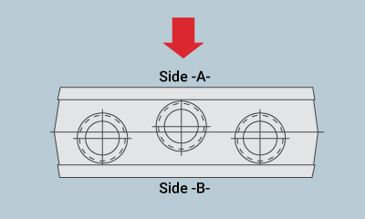
  • A standard metric 3-roller slider has a center bearing that is mounted on an adjustable slide enabling preload. The preload comes preset from the factory but can be adjusted. This roller will contact one side of the rail. (Side “A” in the illustration). The inch series has a fixed preload and cannot be adjusted.
  • The rollers at each end are mounted to contact the opposite side of the rail and will carry the majority of the load (Side “B” in the illustration).
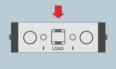
  • Identify which direction to mount the slider so that its two rollers that are designed to carry the majority of the load are oriented correctly. Next, locate the arrows on the face of the slider. Then, install the slider with the arrows pointing in the direction of the force or load being applied. This will ensure that the bearing achieves its rated load capacity.
  • NOTE: Some older versions of the Redi-Rail sliders have a similar design, but the load direction is indicated by two indentations on the slider face instead of two arrows
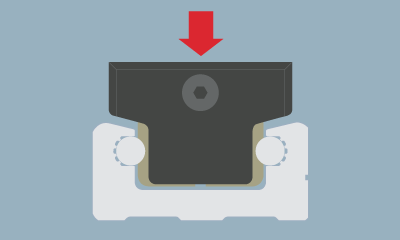
Roller Block Seat

For applications that require an axial load orientation, mount the rails so that the carriage sees the load in the axial (Z) direction. However, keep in mind that the load capacity is much lower than radial loading. Finally, make sure to consult the Cam Roller Technology Catalog for load ratings, or contact an PBC Linear application expert.

Fastening the rails

Within the metric series, the rails have a shallow counter bore which provides very little clearance between the web of the rail and the rollers, and the wipers. Therefore, the correct style of fastener is a button head cap screw (BHCS). The length of the fastener will depend upon how the user is fastening rails to their supporting structure.

Set your pre-load

The final step in the Redi-Rail installation process is to adjust your preload for the linear guide carriages if necessary. While carriages come with a factory-set preload, you have the option of adjusting depending on your application needs. In the video below, we examine our patented side-adjustable preload function. This innovative design offers you easy side-adjustment, especially when compared to other linear guide carriages that require specialized tools. In addition, our side-adjustment design eliminates the need to completely remove any machines, fixtures, or loads prior to adjusting preload. When factoring in the possibility of multiple attempts to fine-tune your preload, it is easy to see how Redi-Rail can dramatically reduce installation time and costs.